
SMART CAR WITH LABORATORY
Utilizing circuits and C++
The objective of this lab is to interface the smart car with an accelerometer sensor and use acceleration readings to direct the car up a ramp while driving backwards. In addition, the car stops at the top of the ramp once the slope is zero. The car uses a closed-loop proportional control feedback loop that utilizes acceleration readings in both the x-axis and y-axis. The steering is controlled using one gain constant and the x-axis acceleration, or side-to-side pitch. The drive motor is controlled using two gain constants, one for side-to-side pitch and another for front-to-back pitch, and both the x-axis and y-axis accelerations. As the x-axis acceleration approaches zero, the car turns less sharply. As the y-axis acceleration deviates from zero, the car drives faster. In addition, when the y-axis acceleration is zero and the x-axis acceleration is non-zero, the car is forced forward to allow the steering system to correct itself and start driving up the ramp. In addition, a buzzer was implemented and turned on and off when the car was driving backwards up the ramp.
This lab provides a chance to interface the Smart Car to another sensor system. Accelerometers are being added to many electronic devices to provide safety as well as convenience features. Being able to detect a free-fall condition may allow a laptop to park a hard drive and prevent a head crash that would render the drive completely useless. Similarly, 3-axis accelerometers can detect orientation of cameras and tablets so that text and graphics are automatically rotated to allow proper viewing.
The module used here is an incredibly sophisticated device that can detect accelerations along all three axes and generate interrupts based on maximum and minimum values in any direction with durations of more than or less than a predetermined period. It also includes a 3-axis compass that measures magnetic field strength in each direction. For this lab, only a subset of all the features will be used. Here the gravitational acceleration in the x and y directions are all that is needed to determine the tilt and direction of a slope. As such, only the 12-bit values associated with the x-axis (oriented as the side-to-side direction, +x to the left) and the y-axis (oriented as the front-to-back direction, +y to the front) when the module is inserted in the protoboard in the ascribed fashion shown below in Figure 5.1.
The module used here is an incredibly sophisticated device that can detect accelerations along all three axes and generate interrupts based on maximum and minimum values in any direction with durations of more than or less than a predetermined period. It also includes a 3-axis compass that measures magnetic field strength in each direction. For this lab, only a subset of all the features will be used. Here the gravitational acceleration in the x and y directions are all that is needed to determine the tilt and direction of a slope. As such, only the 12-bit values associated with the x-axis (oriented as the side-to-side direction, +x to the left) and the y-axis (oriented as the front-to-back direction, +y to the front) when the module is inserted in the protoboard in the ascribed fashion shown below in Figure 5.1.
Finally, this lab still requires the integration of an LCD screen and keypad. As before, the keypad may be used to input the desired heading and to set the steering gain constant. The screen is used to display current heading and the ranger reading. In labs 5 and 6 the LCD and keypad will be used as a way to display and set the gain constants for both heading and altitude. This allows these values to be set on-the-fly, rather than recompiling the program each time a gain is changed. Furthermore, the LCD can be used to display useful values such as the accelerations and gain values.
A radio frequency link will be added to the car to allow for communication between the car and your laptop. This is used to record telemetry data to be sent from the autonomous car to your laptop so that system response data can be plotted. The RF (radio frequency) link appears as another laptop serial port, but requires a new driver. The Gondola Info link on LMS provides the details as does the Drivers for RF link section in the Installing_SiLabs-SDCC-Drivers manual also on the LMS course front page.
With both the RF link and the LCD/keypad panel working, teams will have more flexibility in determining how they will enter parameters and update values. Either system can be used to provide menu-driven instructions for the user.
The integrated software and hardware will result in a car that can detect the direction of the ramp tilt and have the car drive in the direction of the maximum slope until it levels out at the bottom or top. The integrated software should poll the run/stop switch(es) connected to port pin(s) specified by you to start and stop any one or both control functions. There will be similar switches on the Gondola. The details are left up to the team.

Schematic

Proportional gain variable resistor
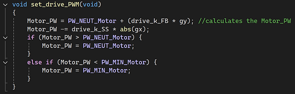
Drive motor power

Steering power / direction
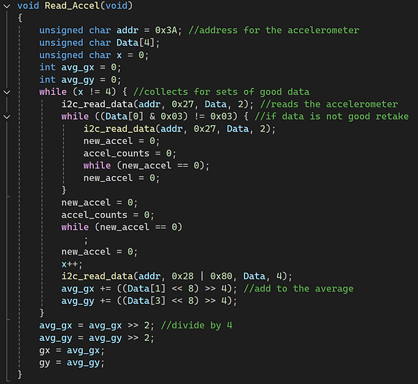
Accelerometer data